
Accurate AHF(Active Harmonic Filter) current rating sizing is the core of efficient power quality management for industrial and commercial power systems. Improper AHF(Active Harmonic Filter) amp sizing—either overrated or underrated—will lead to two major problems: wasted investment and insufficient harmonic suppression, which fails to meet grid THDi standards and triggers equipment overheating, transformer loss, and frequent tripping. For most power engineering designers and on-site engineers, the most reliable and universal sizing method is to calculate the exact AHF(Active Harmonic Filter) current rating based on transformer kVA capacity and actual system THDi level.
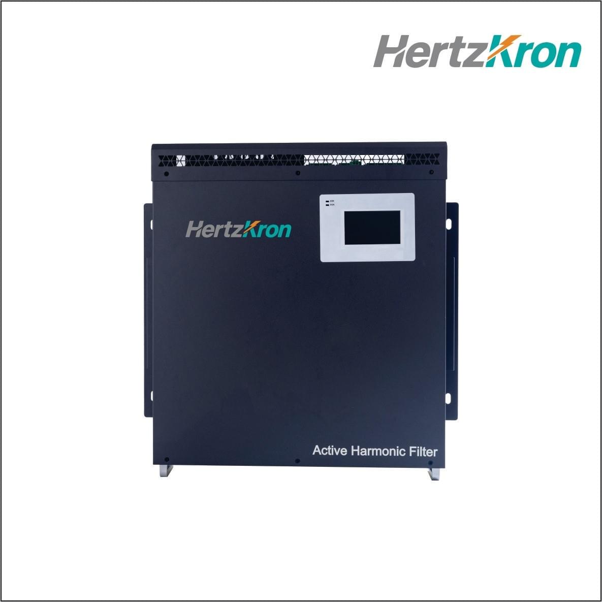
In this guide, we will break down the complete AHF(Active Harmonic Filter) sizing logic, including core calculation formulas, key parameter definitions, step-by-step operation procedures, practical industry cases, and common sizing mistakes, helping you quickly obtain the precise AHF(Active Harmonic Filter) amp rating for your project.
Why Size AHF(Active Harmonic Filter) Current Rating by Transformer kVA & THDi?
Harmonic current is the fundamental working basis of AHF(Active Harmonic Filter) filters. Unlike reactive power compensation equipment, AHF(Active Harmonic Filter) targets harmonic current suppression, and its rated current directly determines the maximum harmonic governance capacity.
The transformer is the core power supply carrier of the entire low-voltage system. Its kVA capacity defines the upper limit of the system’s total load current, while the THDi (Total Harmonic Distortion of Current) reflects the severity of on-site harmonic pollution. Combining these two core parameters can fully restore the actual harmonic current of the system, ensuring the AHF(Active Harmonic Filter) size matches the on-site working conditions perfectly.
Blind sizing by experience only leads to hidden risks: undersized AHF(Active Harmonic Filter) cannot filter out high-order harmonics thoroughly, resulting in persistent excessive THDi; oversized AHF(Active Harmonic Filter) increases procurement and operation costs and causes low equipment utilization.
Core AHF(Active Harmonic Filter) Current Sizing Formula (Industry Standard)
The centralized harmonic governance sizing formula based on transformer kVA and THDi is widely recognized and adopted in the power industry, applicable to 400V low-voltage distribution systems in factories, commercial buildings, data centers, and other scenarios:
Ih = [ S × K / ( sqrt(3) × U × sqrt(1 + THDi²) ) ] × THDi
Parameter Detailed Explanation
- Ih: Calculated harmonic current (A), the core basis for AHF(Active Harmonic Filter) rated current selection
- S: Transformer rated capacity (kVA), the fixed parameter of the project’s power distribution system
- K: Transformer load rate, the empirical value of actual on-site operation (standard range: 0.6–0.8; 0.7 is recommended for general industrial scenarios)
- U: System line voltage (V), default 400V for conventional low-voltage systems
- THDi: Actual system current total harmonic distortion, measured on-site or defined by industry standards
After calculating the Ih value, we need to reserve a 10%–30% safety margin according to the load fluctuation to determine the final AHF(Active Harmonic Filter) rated current, avoiding overload operation during peak load periods.
Step-by-Step AHF(Active Harmonic Filter) Current Rating Sizing Process
Mastering the standardized process can eliminate calculation errors and ensure accurate and efficient sizing. The complete operation steps are as follows:
Step 1: Confirm Basic System Parameters
Collect core on-site data first, including transformer kVA capacity, low-voltage side rated voltage, and actual operating load rate. For newly built projects without operating data, adopt the industry conventional load rate of 0.6–0.8; for renovated projects, take the actual measured average load rate.
Step 2: Test or Confirm System THDi Level
THDi is the key parameter affecting AHF(Active Harmonic Filter) sizing. Different industrial scenarios have obvious differences in THDi:
- Ordinary lighting and commercial loads: THDi ≈ 5%–15%
- General manufacturing factories (motor, pump loads): THDi ≈ 15%–25%
- High-harmonic scenarios (frequency converter, rectifier, welding equipment): THDi ≈ 25%–40%
It is recommended to use a power quality analyzer to test the actual THDi value of the system for the most accurate sizing.
Step 3: Calculate Theoretical Harmonic Current
Substitute the collected transformer kVA, load rate, voltage, and THDi data into the core formula to calculate the theoretical harmonic current Ih of the system.
Step 4: Add Safety Margin & Confirm AHF(Active Harmonic Filter) Rating
Considering load peak fluctuation, future equipment expansion, and long-term operation attenuation of AHF(Active Harmonic Filter), add a 20% safety margin on the basis of the calculated Ih value, and select the standard AHF(Active Harmonic Filter) rated current specification closest to the calculated value.
Practical Sizing Case (Real Industrial Scenario)
Take a typical industrial factory project as an example to demonstrate the full calculation process:
Project Basic Parameters:
- Transformer capacity S: 1600kVA
- System voltage U: 400V
- Transformer load rate K: 0.7 (long-term stable operation)
- Actual measured system THDi: 30% (high harmonic caused by frequency conversion equipment)
Calculation Process:Ih = [ 1600 × 0.7 / ( sqrt(3) × 400 × sqrt(1 + 0.3²) ) ] × 0.3 ≈ 465A × 0.3 ≈ 139.5A
Final Sizing Result:After adding 20% safety margin: 139.5 × 1.2 ≈ 167A. Select the standard 175A AHF(Active Harmonic Filter) to meet the long-term stable harmonic suppression demand, and the system THDi can be reduced to below 5% after governance.
Common AHF(Active Harmonic Filter) Sizing Mistakes to Avoid
1. Ignoring Transformer Load Rate
Many engineers directly use the transformer full-load current for calculation, resulting in excessively large AHF(Active Harmonic Filter) selection and cost waste. Most transformers operate at 60%–80% load for a long time, and the load rate must be included in the calculation to fit the actual working conditions.
2. Sizing Without THDi Data
Blindly configuring AHF(Active Harmonic Filter) by transformer capacity alone is the most common mistake. The same 1000kVA transformer has a 5-fold difference in harmonic current between low THDi (10%) and high THDi (40%) scenarios, which directly determines the AHF(Active Harmonic Filter) current rating.
3. No Safety Margin Reserved
If the AHF(Active Harmonic Filter) is selected according to the theoretical calculated value without margin, it will be overloaded during peak load or seasonal load fluctuation, leading to reduced filtering efficiency, equipment alarm or damage, and shortened service life.
4. Disregarding Industry Harmonic Characteristics
High-frequency harmonic loads such as rectifiers and UPS produce more complex harmonic components. It is necessary to appropriately increase the safety margin on the basis of conventional calculation to ensure full-spectrum harmonic suppression.
Key Tips for Optimized AHF(Active Harmonic Filter) Sizing
- For stable-load scenarios (commercial buildings, office buildings), a 10%–15% safety margin is sufficient; for fluctuating industrial loads, a 20%–30% margin is recommended.
- When the system is planned to expand equipment in the future, appropriately increase the AHF(Active Harmonic Filter) current rating in advance to avoid secondary replacement and transformation.
- For distributed harmonic sources, centralized governance based on total transformer capacity is preferred; for single high-harmonic equipment, local targeted AHF(Active Harmonic Filter) sizing can reduce overall investment.
- After sizing, verify the matching degree between AHF(Active Harmonic Filter) rated current and system short-circuit current to ensure safe and stable operation of the equipment.
Final Summary
Sizing AHF(Active Harmonic Filter) current rating based on transformer kVA and THDi level is the most scientific, accurate and cost-effective industry standard method. The core logic is to restore the actual system harmonic current through transformer capacity, load rate and THDi data, and match the AHF(Active Harmonic Filter) rated current with a reasonable safety margin.
Standardized sizing can not only perfectly solve power quality problems such as excessive harmonics, equipment heating and grid instability, but also maximize the cost performance of AHF(Active Harmonic Filter) equipment, avoid over-investment and insufficient governance. For all low-voltage power quality renovation and new construction projects, this kVA + THDi dual-dimensional sizing method is worthy of universal promotion and application.
FAQs About AHF(Active Harmonic Filter) Current Rating Sizing
Q1: Can AHF(Active Harmonic Filter) be sized only by transformer kVA without THDi data?A: It is not recommended. Transformer capacity only reflects the total load, while THDi determines the harmonic content. Sizing without THDi will lead to large errors and cannot ensure filtering effect.
Q2: What is the best safety margin for AHF(Active Harmonic Filter) sizing?A: 20% is the universal standard. Stable loads adopt 10%–15%, and fluctuating heavy industrial loads adopt 25%–30%.
Q3: Is this formula applicable for all low-voltage systems?A: Yes, it is suitable for all 400V three-phase low-voltage distribution systems, covering industry, commerce, education, medical treatment and other scenarios.